JEE Main 2025 Jan 22 Shift 2, Physics Q13: Logic Gates
JEE Main2025Jan 22, Shift 2Physics
Learn this concept: Logic Gates →
Q.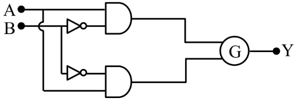
To obtain the given truth table, following logic gate should be placed at G :
| A | B | Y |
|---|---|---|
| 0 | 0 | 1 |
| 0 | 1 | 0 |
| 1 | 0 | 0 |
| 1 | 1 | 1 |
- A
NOR Gate
- B
AND Gate
- C
NAND Gate
- D
OR Gate
Solution
Given
- Upper AND gate gets and
- Lower AND gate is meant to get and
- Required output for
Idea only when , so is XNOR, which is the complement of . Test each gate on the two AND outputs.
Steps
Write Y from the table
From the table, is 1 only when .
Key step only when , so is XNOR, the complement of .Find the two AND outputs
Upper AND output: . Lower AND output: . In the figure both inverters are drawn on line B. Read literally, that makes as well, and then no option gives the table. The circuit only works with the lower inverter on line A, so is used.
Tabulate P and Q
For : and .
Rule out OR, AND, NAND
OR: , which does not match. AND: , which does not match. NAND: , which does not match.
NOR matches
NOR gives . This matches the table.
AnswerOption A: NOR Gate
Faster wayAt both AND outputs are 0, yet , so G must give 1 for inputs ; only NOR and NAND do this. At the inputs to G are and . NAND would give 1 here, so G is NOR.
TrapA student who sees that the circuit forms picks the OR gate, Option D. This gives XOR (), which is the exact complement of the required table.
Concept behind this question
Logic GatesNotes, formulas and examples →More previous year questions on Logic Gates
Practice more Physics
Concept-wise practice with instant solutions on Fundamenthol.
Start practicing →